PM5544 / PM5644
Test pattern generator
A real Philips test pattern from a Raspberry Pi. The PM5644 is read live from the original EPROM data, the classic PM5544 is reconstructed pixel by pixel. Straight onto the composite output, with your own call, a running clock and text. Free, and measurably good.
Widescreen signal on line 23 (WSS). With the 16:9 cards a signal now goes along that tells a widescreen TV the picture is 16:9, so it switches over by itself. The 4:3 cards say 4:3. The Pi cannot really do that, so the bits are drawn pixel by pixel into picture line 23, exactly 11.0 µs after the sync. On a Pi 4 the encoder does do it itself, and there the same is also set in the register. So the same card works on both. It can be switched off with one button.
New card: ITU-R BT.1729 16:9. The official widescreen reference card, with the ball that bounces through it like ping-pong. Drawn from the vector version by T. Sato (public domain), calculated anamorphically on 720x576.
The text is readable everywhere. Around the callsign, the QTH, the clock and the date there is now a soft black outline, even in the middle of a busy or light card. Adjustable from 0 to 2 pixels on the control page; at 0 it is gone.
Small preview pictures in the menu. Next to each card button is a thumbnail of that card, taken straight from what is really sent out.
Which Pi? From a Pi 3 it runs well, on a Pi 4 it runs smoothly. On a Pi 1 or Pi 2 the test cards are fine, as with version 3, but the moving things (clock hands, waving and scrolling text, the ball) stutter. A Pi 1 is unsuitable for that and a Pi 2 really too; we do not recommend them.
19 test cards instead of 11. Added: PM5540 black and white, EBU mono, FuBK 4:3 with and without ring, FuBK 16:9, BBC ETP-1, a card in BBC test card style, a station clock with analogue hands, colour bars 100% and your own photo.
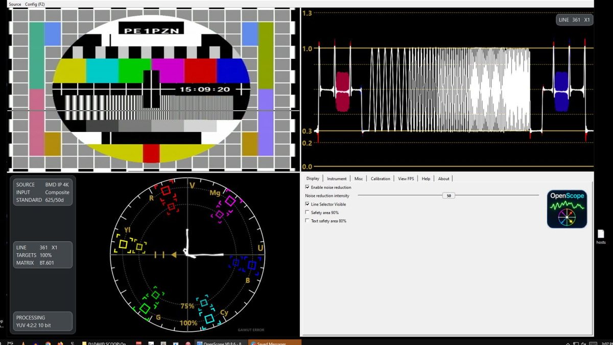
The measurement cards are calculated instead of scaled. In the pictures that go around everywhere the multiburst is broken: it is drawn as a square wave and aliases, and after scaling only a fraction of the amplitude is left. Here every card has a real sine at fs = 13.5 MHz, from 0.8 to 4.8 MHz, over the full amplitude. Measured on the composite output: flat within 0.2 dB over the whole band.
The PM5644 16:9 has been repaired. That ROM delivers 1040 samples at 20 MHz, and they were squeezed to 720 with the wrong method. The card was stretched by 2.5% and the high bursts sagged. Now it is right to the kilohertz.
You can now put it on your own network. Fill in your Wi-Fi name and password
on the control page, or beforehand in the file netwerk.txt on the SD card. The
latter is handy if you have a Pi without a network connector, like a Zero 2 W:
then you do not even have to go in via its own Wi-Fi point. A fixed IP address on the
network cable is possible too, and you can give the Pi's own Wi-Fi network a name of its own,
for example your callsign.
And you will not lose it. After start-up the address where you reach the Pi
is shown at the bottom of the test pattern, with LAN or WIFI in front. As soon as you open the control page
it disappears by itself. If connecting fails, the Pi switches its own
network back on within a minute. And if it still goes wrong, simply empty netwerk.txt on the card
again.
And further: analogue hands and waving or scrolling text over any card, upload your own photo from the control page and use it straight away as a test card, all settings remembered per card, and save your own setup and restore it with one click.
If you transmit ATV, test your repeater, or simply want to align a monitor, you want a decent test pattern. Not a blurry picture from the internet, but a real PAL signal with the right geometry, colours and frequencies. That is exactly what this little box does: a Raspberry Pi delivering a broadcast test pattern on its composite output.
Really read out, not a screenshot
The PM5644 (the well-known digital Philips test pattern, 4:3 and 16:9) is not shown as a picture, but decoded live from the original EPROM data, a port of the real generator. The classic PM5544 has been reconstructed by hand. Both at the authentic 720×576, with the real PM8546 text generator font for your call, QTH, clock and date. Scaling down uses hard pixels (nearest), so the lines stay sharp, no blurring.
The multiburst is right, and you can measure it
The difference from an arbitrary test pattern is in the details. The multiburst runs cleanly from 0.8 to 4.8 MHz (the upper limit for PAL System B/G), flat within ±0.2 dB on the waveform monitor. The 16:9 version is correctly squeezed anamorphically. Everything has been measured on real broadcast equipment, because a test pattern that only looks good is not enough.
Simple to operate
The Pi starts straight into the test pattern, no HDMI or screen needed. You operate it wirelessly: the Pi creates its own Wi-Fi (no router needed) and on a web page you choose the card, fill in your call and QTH, and switch on the clock, date, a moving bar or scrolling text. All fine adjustment is in a separate tab, so you do not touch it by accident in daily use.
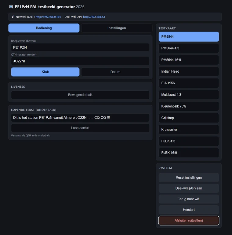
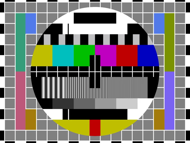
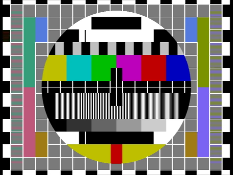
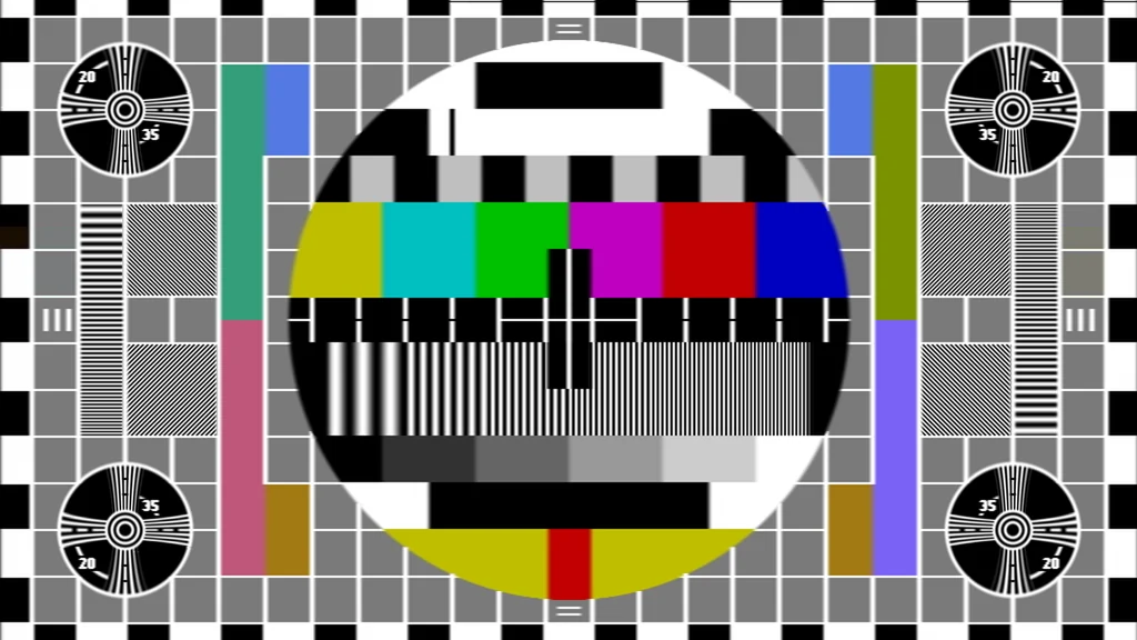
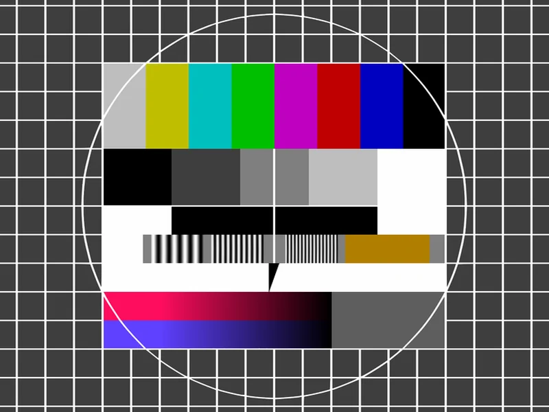
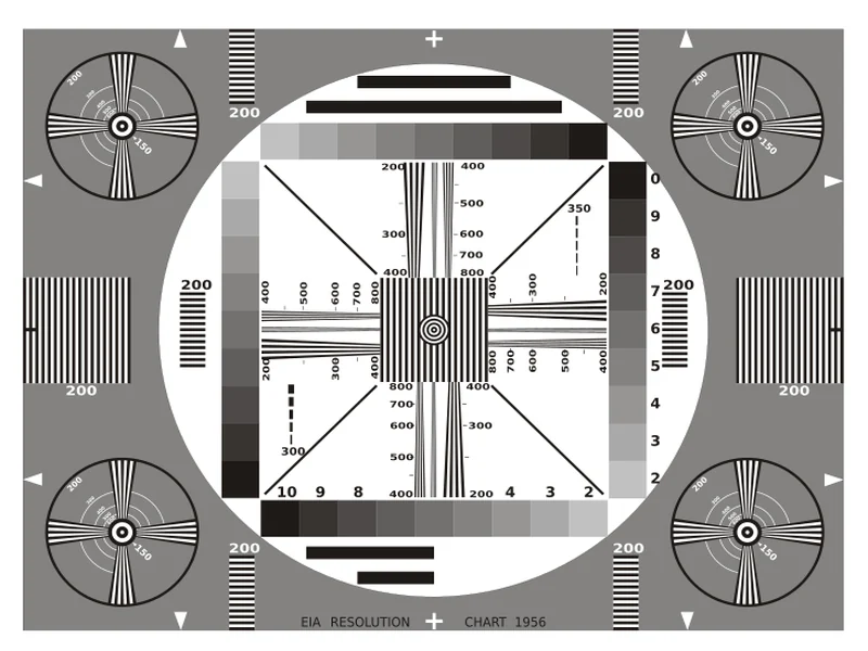


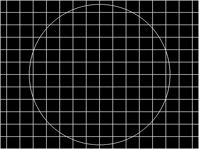

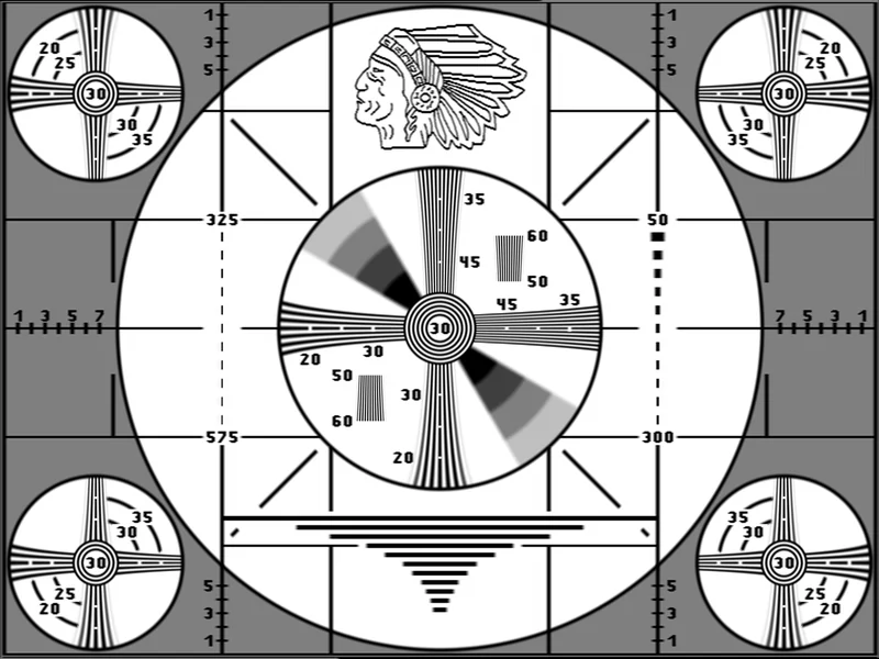
Every card with your own call, QTH, clock and date, right in the picture. The FuBK also comes in 16:9.
HARDWARE
SIGNAL
Do not connect HDMI
The Pi sends the test pattern to the composite output. If an HDMI cable is plugged in, the Pi automatically chooses that screen and the composite output stays empty. So simply leave HDMI out, you do not need it.
Where does the video signal come out?
On a Pi 3, 3B+ or 4 the video comes out of the 3.5mm jack, the same one as the audio. Note: that is a 4-pole (TRRS) connector. Besides audio left/right it also carries the composite video, on the last contact ring. So you need a 4-pole TRRS-to-RCA cable.
No jack? Solder underneath
If you have a Pi without an AV jack, or want a fixed connection, there are solder pads for composite video on the board. Solder a wire with an RCA plug to it (video + ground) and you still have a picture. For the average amateur a piece of cake.
The Pi 5 does not work
This image does not run on the Pi 5. It does have solder points for composite video, but no longer the old graphics layer this test pattern uses to put the PAL signal on the composite output. So it is not the cable, and soldering does not solve it either. Take a Pi 3B.
Other models: allowed, but your own choice
This was made and tested on a Pi 3B. From a Pi 3 it runs well, on a Pi 4 it runs smoothly. The Zero 2W also works well; it has the same processor as the Pi 3. On a Pi 1 or Pi 2 the test cards are fine, as with version 3, but everything that moves stutters: the analogue hands, the waving and scrolling text, the moving bar and the ball of the BT.1729. A Pi 1 is unsuitable for that and a Pi 2 really too, so we do not recommend them. If you switch those moving things off, you still have a fine still test pattern on such an old Pi.
Do mind what such a board does and does not have. The Pi 1 and 2 have no Wi-Fi: there you can only reach the control page via the network cable, and then you have to look up the IP address on your network yourself. The Zero 2W has no network connector: there it always goes via the generator's own Wi-Fi point, so with your phone or laptop. On a Pi 3B you have both and everything works as described in the manual. Such a Pi 3B costs about 39 euros.
Made by PE1PzN. Free to use and share among radio amateurs. Questions or improvements? I would like to hear them.